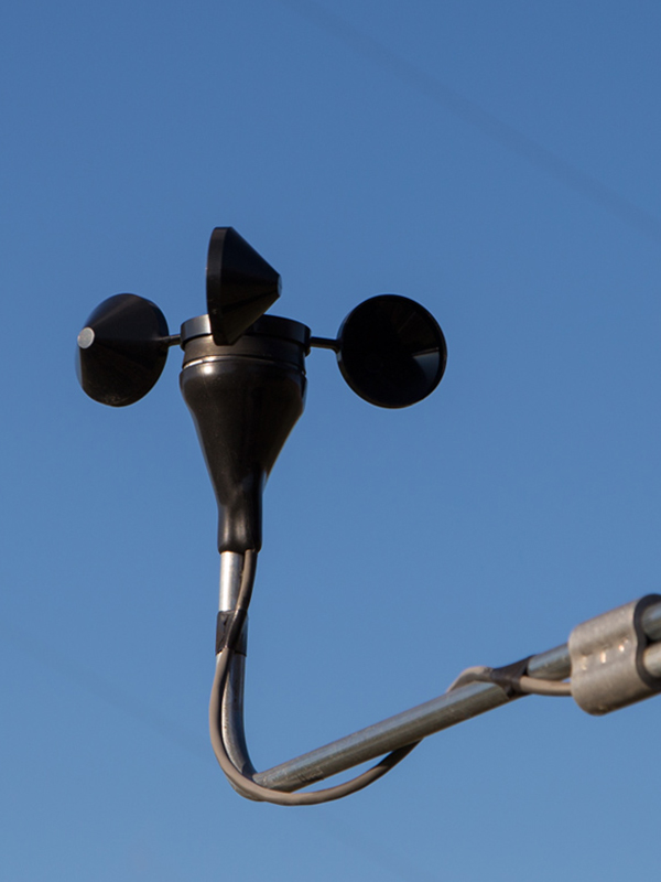
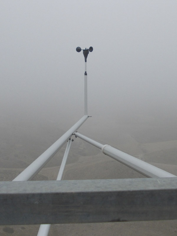
The NRG 40 anemometer is designed for the acquisition of wind speed.
NRG 40C
The 40C bearings and low moment of inertia permit very rapid response to gusts and lulls. A four-pole magnet induces a sine wave voltage into a coil, producing an output signal with frequency proportional to wind speed.
NRG 40H
The 40H is based on the NRG 40 C. This Hall Effect version is engineered for electrically noisy environments and instrumentation that requires a square wave signal.
The 40H’s Hall Effect switch produces a high-level square wave voltage signal with a frequency proportional to wind speed. This signal is easy to interface to a wide range of industrial devices including turbine controllers, programmable logic controllers (PLCs), and data loggers. A 5-26V DC excitation voltage with 5 mA of current is required.
Both of the anemometers are constructed of rugged Lexan cups, the 40H is molded in one piece for repeatable performance. A PVC terminal boot is included with each anemometer for additional protection from the elements.
The specifications below are from the NRG 40C
| DESCRIPTION | |
| Sensor type | 3 Cup Anemometer |
| Applications | Wind resource assessment
Meteorological studies
Environmental monitoring |
| Sensor range | 1 m/s to 96 m/s |
| OUTPUT SIGNAL | |
| Signal type | Low level AC sine wave, frequency linearly proportional to wind speed |
| Anemometer Transfer Function | Consensus Transfer Function:
Scale Factor (Slope): 0.765 m/s/Hz
Offset: 0.35 m/s |
| Output voltage at threshold | 80 mV (peak-to-peak) minimum |
| Output voltage at 60Hz | 12 V (peak-to-peak) typical
Output amplitude NOT proportional to wind speed
Output amplitude NOT proportional to wind speed |
| Output signal range | 0 Hz to 125 Hz (at 96m/s, highest recorded) |
| RESPONSE CHARACTERISTICS | |
| Distance constant (63% recovery) | 2.55 m at 5m/s per ASTM D 5096-02
2.56 m at 10m/s per ASTM D 5096-02 |
| Swept diameter of rotor | 190 mm |
| INSTALLATION | |
| Mounting | Onto a 13 mm diameter mast with cotter pin and set screw |
| Tools required | 0.25 inch nut driver, petroleum jelly, electrical tape |
| ENVIRONMENTAL | |
| Operating temperature range | -55 °C to 60 °C |
| Operating humidity range | 0 to 100% RH |
| PHYSICAL | |
| Connections | 4-40 brass hex nut/post terminals |
| Weight | 0.14 kg |
| Dimensions | 3 cups of conical cross-section, 51 mm dia.
81 mm overall assembly height |
| MATERIALS | |
| Cups | One piece injection-molded black polycarbonate |
| Body | Housing is black ABS plastic |
| Shaft | Beryllium copper, fully hardened |
| Bearing | Modified Teflon, self-lubricating |
| Magnet | Indox 1, 25 mm diameter, 13 mm long, 4 poles |
| Coil | Single coil, bobbin wound, 4100 turns of #40 wire, shielded for ESD protection |
| Boot | Protective PVC sensor terminal boot included |
| Terminals | Brass |


