
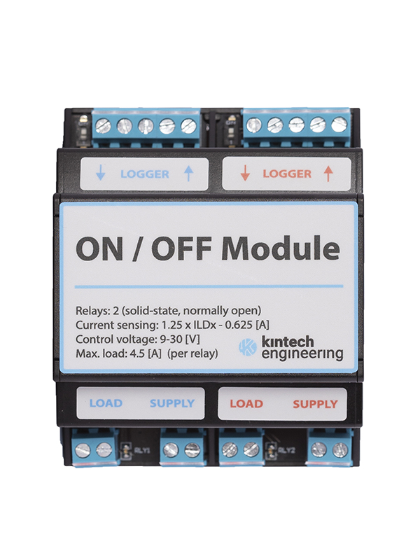
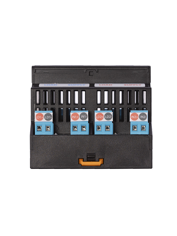
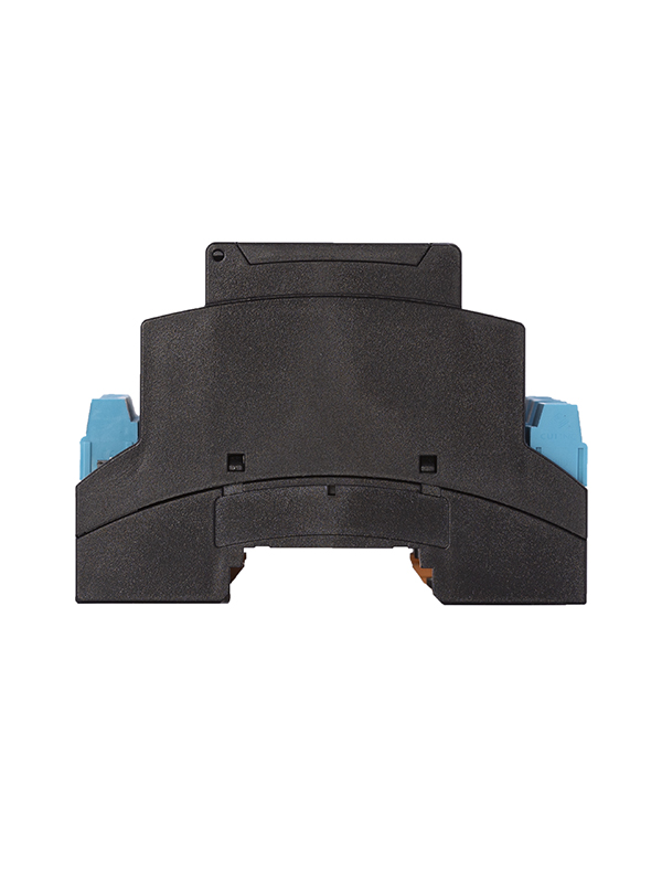


The ON/OFF Module uses the control signals of any of the six programmable outputs featured in the Orbit 360 data logger to connect or disconnect a load from its power supply. Each module comprises two solid-state relays, enabling the control of two independent power circuits.
Solid-state relays (SSRs) are electronic switching devices that activate or deactivate when an external voltage is applied to their control terminals. While they serve the same purpose as electromechanical relays, they consume significantly less power than conventional electromechanical relays and have no moving parts, resulting in a longer operational lifespan. By integrating an on-chip optocoupler, the SSR also ensures that the control is electrically isolated.
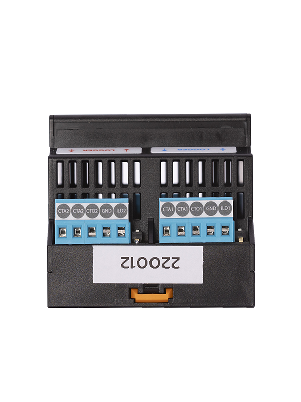
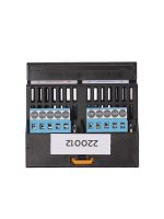
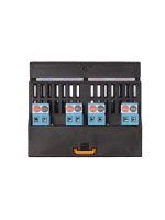
Up to three outputs can be used to control each module by means of Boolean AND / OR logic (see diagram on page 3 of the datasheet). Typical use for the AND logic would be to activate a signal when, for instance, the temperature falls below 0ºC AND the relative humidity goes beyond 70%. When a single signal is sufficient to control the relay activation, leave the CTAx terminals unconnected and just connect the control signal to the CTOx terminal. Each relay is assigned an LED that indicates whether it is open/inactive (LED off) or closed/activated (LED on).
In order to detect failures on both the load side (such as a broken beacon) and the power side (such as a dead battery), the ON/OFF module includes two outputs that monitor the current flowing through each relay. These outputs can be connected to any analog channel of the logger. The current is measured by hall effect, thus maintaining galvanic isolation between the power and control sides. Two microswitches allow the user to disconnect the Hall meters to save consumption in case they are not going to be used.
The transfer function relating the module ILDx output to the current through relay x is as follows:
Current through Relay 1 [A] = 1.25 x ILD1 – 0.625
Current through Relay 2 [A] = 1.25 x ILD2 – 0.625
In case you want to monitor the voltage together with the current measurement, a commercial voltage divider from Kintech Engineering can be used, connected to a separate analog channel of the data logger.
